2. Encoding and Modulation
Data Communication & Networking
3rd Semester
Encoding Techniques
- Digital Data, Digital Signal
- Analog Data, Digital Signal
- Digital Data, Analog Signal
- Analog Data, Analog Signal
Digital Data, Digital Signal
- Discrete, Discontinuous voltage pulses
- Binary data encoded into signal elements
- Each pulse is a signal element
Common Terms
- Unipolar
- All signal elements have the same sign
- Polar
- One logic state by positive and other by negative
- Data rate
- Rate of transmission bits per second
- Duration / Length of bit
- Time taken for transmitter to emit the bit
- Encoding
- Take a digital signal and convert it into a suitable form for sending on a wire
- Modulation
- Take a signal and modifies a carrier signal with it
- Modulation Rate
- Rate at which signal level change
- Measured in baud
- Mark | Space
- Binary 1 | Binary 0
Baseband vs Broadband
- Baseband
- Digital Signals: Entire medium carries only one signal at a time
- Analog Signals: Original Frequency range of an analog signal before it’s modulated
- Broadband
- Carries two or more data in separate channels
Encoding Schemes
- Nonreturn to Zero-Level (NRZ-L)
- Nonreturn to Zero Inverted (NRZI)
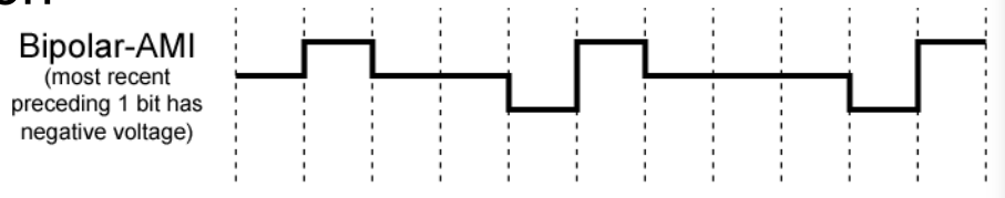
- Bipolar -AMI
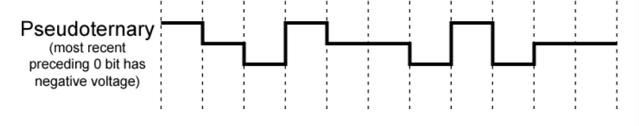
- Pseudoternary
- Manchester
- Differential Manchester
- B8ZS
- HDB3
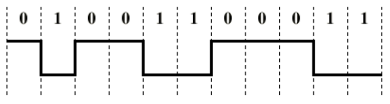
Nonreturn to Zero-Level (NRZ-L)
- Two different voltages for 0 and 1
- Voltage constant during bit interval
- Zero voltage for 0, Positive voltage for 1
- Sometimes negative voltage for zero
Nonreturn to Zero Inverted
- Nonreturn to zero inverted on ones
- Constant voltage pulse for duration bit
- Data encoded as presence or absence of signal transition at beginning of bit time
- Transition denotes a 1
- No transition denote a 0
- An example of Differential Encoding

Differential Encoding
- Data represented by changes
- Advantages
- More reliable detection of transition
- Disadvantages
- In complex layouts it’s easy to lose sense of polarity
NRZ pros and cons
- Pros
- Easy to engineer
- Make good use of bandwidth
- Cons
- DC component
- Lack of Synchronization
- Used for magnetic recording
- Not often used for signal transmission
Multilevel Binary
- Use more than two levels
- Bipolar AMI (Alternate Mark Inversion)
- 0
No signal - 1
Positive or negative pulse - Pulse alternate in polarity
- No loss of sync if a long string of ones, (not good for long zeroes)
- No net DC component
- Low bandwidth
- Easy error detection
- 0
Pseudoternary
- 1
No signal - 0
Alternating positive and negative - No advantage or disadvantage over bipolar-AMI
Trade Off for multilevel binary
- Not as efficient as NRZ
- Each signal only represent one bit
- In 3 level system could represent
bits - Receiver must distinguish between three levels
- Requires 3dB more signal power for same probability of bit error
Biphase
Manchester
- Transition in middle of each bit period
- Transition serves as clock and data
- LOW
HIGH 1 - HIGH
LOW 0 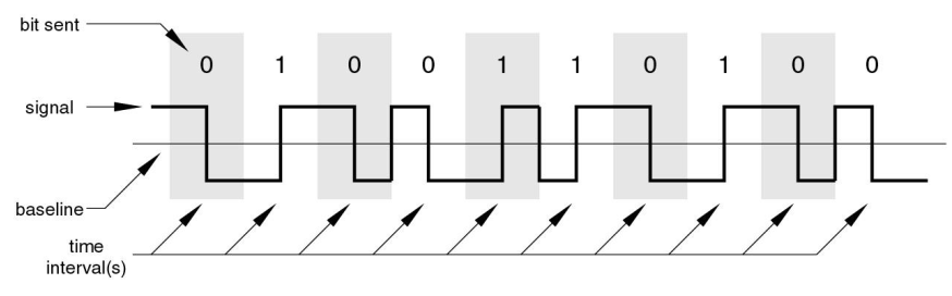
Differential Manchester
- Midbit transition is clocking only
- Transition at start of a bit
0 - No transition at start of bit
1 - This is a differential encoding scheme

Biphase Pros and Cons
- Con
- At least one transition per bit time or two
- Max modulation rate is twice NRZ
- Require more bandwidth
- Pros
- Synchronization on mid bit transition
- No dc component
- Error detection
Scrambling
- Use scrambling to replace sequences that produce constant voltage
- Filling sequence
- Must produce enough transitions to sync
- Must be recognized by receiver and replace with original
- Same length as original
- No dc component
- No long sequences of zero level line signal
- No reduction in data rate
- Error detection capability
B8ZS
- Bipolar with 8 zeros substitution
- Based on bipolar-AMI (Alternate Mark Inversion)
- Solves the problem where
- If 8 continuous zeroes and previous pulse is positive, encode as 000+-0-+
- If a pulse is + and there are 8 zeroes after that, then encode it as 000+-0-+ this causes an AMI violation because the 4th item is + and the previous pulse is also + the second AMI violation occurs at position 7
- If 8 continuous zeros and previous pulse is negative, encode as 000-+0+-
- If a pulse is - and there are 8 zeroes after that, then encode is as 000-+0+- this causes an AMI violation because the 4th item is - and the previous pulse is also - the second AMI violation occurs at position 7
- Causes two violations of AMI code
- Unlikely to occur as a result of noise
- Receiver detects and interprets as octet of all zeros
HDB3
- High Density Bipolar 3 Zeros
- Based on Bipolar-AMI
- String of four zeroes replaced with one or two pulses

Digital Data, Analog Signal
- Amplitude shift keying (ASK)
- Frequency shift keying (FSK)
- Phase shift keying (PK)
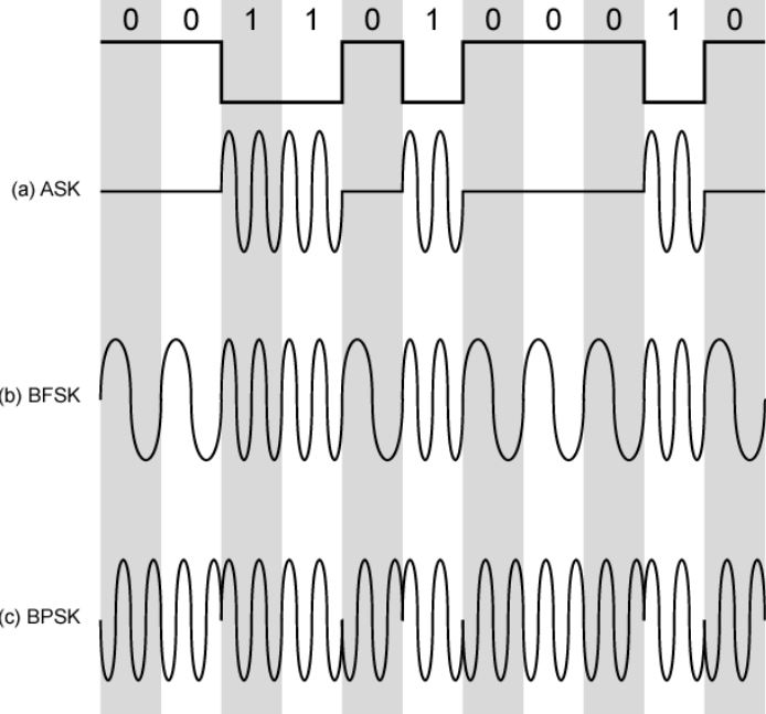
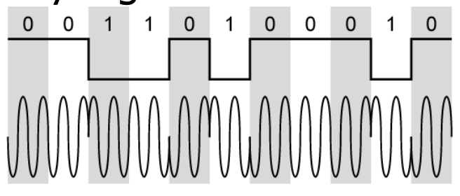
Amplitude Shift Keying
- Values represented by different amplitudes of the carrier wave
- One amplitude is zero
- Susceptible to sudden gain changes
- Inefficient
- Up to 1200bps on voice grade lines
- Used over optical fiber
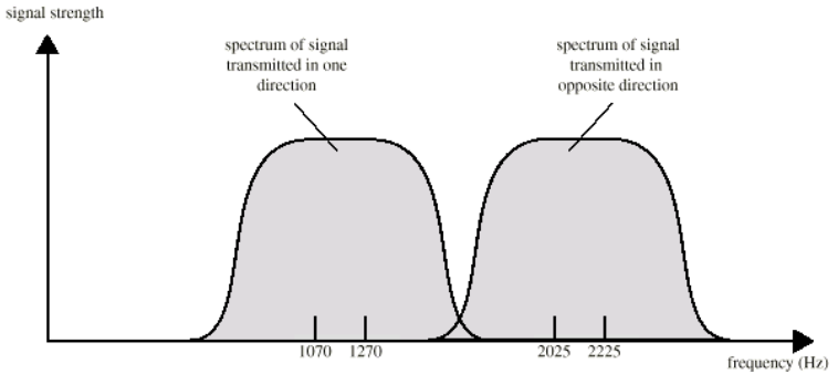
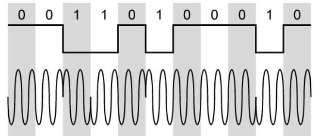
Binary Frequency Shift Keying
- Two binary values represented by two different frequencies
- Less susceptible to error
- Upto 1200bps on voice grade lines
- High frequency radio
- Even higher frequency on LANs using co-ax
Phase Shift Keying
- Phase of carrier signal is shifted to represent data
- Binary PSK
- Two phases represent two binary digits
- Differential PSK
- Phase shifted relative to previous transmission rather than some reference signal
| BPSK | DPSK |
|---|---|
 |  |
Quadrature PSK
- More efficient
- Each element represent more than one bit
- Eg: Shifts of
can represent two bits - Can use 8 phase angles and have more than one amplitude
- 9600bps modems use 12 angles, four of which have two amplitudes
- Eg: Shifts of
Performance of Digital to Analog Modulation Schemes
- Bandwidth
- for ASK and PSK bandwidth is directly related to bit rate
- FSK bandwidth related to
- Data rate for lower freq
- Offset of modulated freq from carrier at high freq
Quadrature Amplitude Modulation
- Used on ADSL and some wireless
- Combination of ASK and PSK
- Logical extension of QPSK
- Send two different signals simultaneously on same frequency
- Use two copies of career, one shifted
- Each carrier is ASK modulated
- Two independent signals over the same medium
- Demodulate and combine for original binary input
- Use two copies of career, one shifted
Analog Data, Digital Signal
- Digitization
- Conversion of analog data into digital data

- Conversion of analog data into digital data
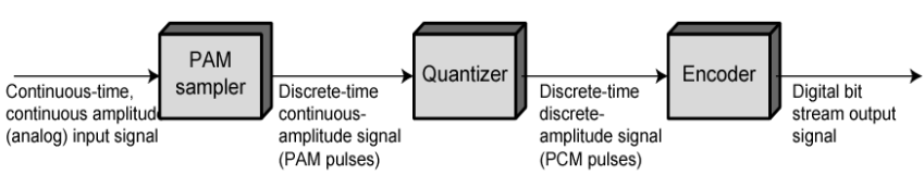
Pulse Code Modulation (PCM)
- Signal is sampled at regular intervals, each sample assigned a digital value
- Ex: 4 Bit signal gives 16 levels
- Quantized
- Quantizing error or noise
- Approximation : Can’t recover original exactly
- Ex: 8000 samples per second of 8 bits gives 64kbps
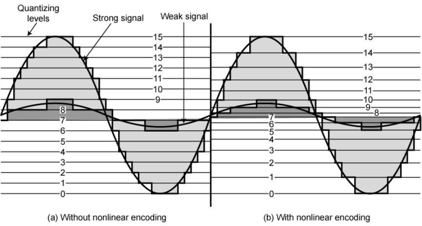
Nonlinear Encoding
- Quantization levels not evenly spaced
- Reduce overall signal distortion
- Can also be done by companding
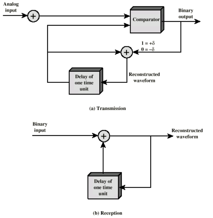
Delta Modulation
- Analog output is approximated by a staircase function
- Move up or down one level at each sample interval
- Binary behavior
- Function moves up or down at each sample interval
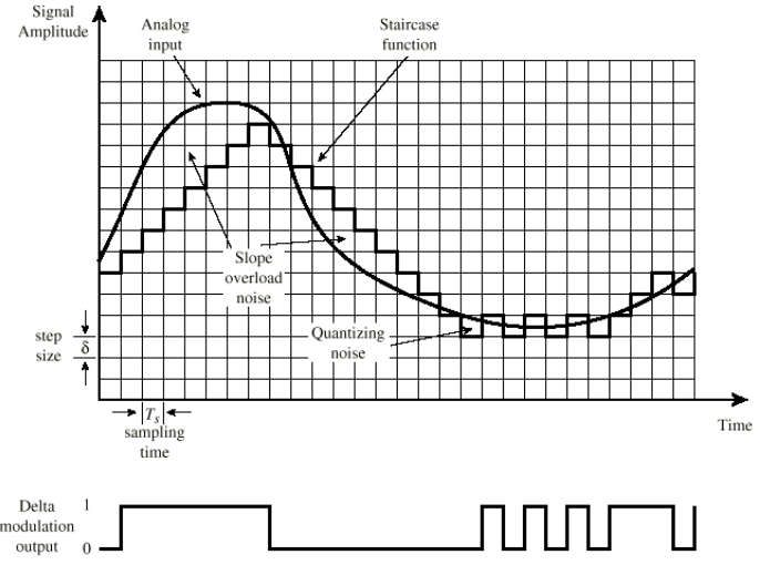
- Function moves up or down at each sample interval
- Good Voice reproduction
- PCM - 128 levels (7bit)
- Voice bandwidth 4KHz
= 56kbps
- Data compression can improve on this
- Eg: Interframe coding techniques for video
Analog Data, Analog Signals
- Why modulate analog signals?
- Higher frequency can give efficient transmission
- Permit frequency division multiplexing
- Types of modulation
- Amplitude
- Frequency
- Phase
Amplitude Modulation (AM)
- Amplitude of a carrier signal is altered
- Frequency of the carrier is usually greater than the highest frequency of the input signal*